 Course 6
Can you see the flow from power change? (Part 2)
Course 6
Can you see the flow from power change? (Part 2)
In the previous session, Max, who is in his third year as a chemical engineer, answered quite well to his senior 's questions.?
The first question is about the reason why the consumption power is different between two mixing vessels.
The other is how much the rotation speed of the impeller can be increased.
Max had thoroughly understood and learned the “Three Principles of Mixing”, so that he was able to answer the questions immediately on the spot. Let's start with knowing the “Three Principles of Mixing”, which are rules of flow during mixing.
<Three Principles of Mixing>
Principle 1
In an actual vessel (with a size of around 10 m3), Flow condition in the vessel is not in the laminar flow region, but in the inertia force-dominated turbulent flow region, provided the viscosity is not significantly high (1,000 mPa・s or higher).
Principle 2
In the turbulent flow region, the power is significantly affected by the internals (baffle and others), and therefore the baffle conditions should be confirmed.
Principle 3
In the turbulent flow region (with baffles), the flow is dominated by inertia force, and therefore the power is proportional to the first power of the density and the cube of the rotation speed.
As long as these three principles and the Np-Re (Power number vs Reynolds number) curve are kept in mind, you can judge the applicability by imagining what region the flow is in from the operating conditions of the mixing vessel.
Then, let us explain how Max thought on the spot, using simple equations.
Figure 1. Np-Re curve
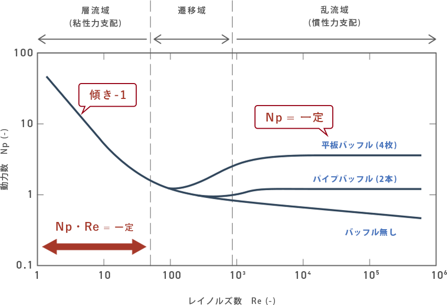
Principle 1: At the actual scale, mixing vessels usually runs in the turbulent flow region.
There are two types of fluid flow: a laminar flow and a turbulent flow. A laminar flow is an orderly flow which velocity components are zero except that in the flow direction, and a turbulent flow is an irregular flow having velocity components not only in the flow direction but in three-dimensional directions.
As a familiar example, suppose when you turn on the water faucet. If you turn the faucet a little, a small amount of water runs smoothly, but if you turn the faucet wide open to run much water, water runs down violently. The former is a laminar flow, and the latter is a turbulent flow.
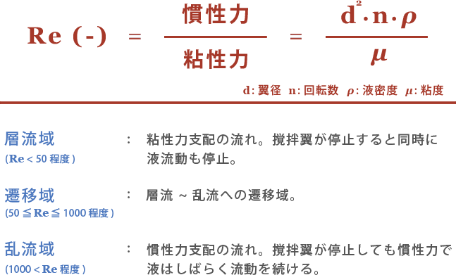
Such states of flow called laminar flow and turbulent flow can be digitized using an index called “Reynolds number”. The Reynolds number is a dimensionless number, which indicates the flow in a mixing vessel. In a mixing vessel, there are inertia force, which is a force to continue flowing, and a viscous force, which resists the flow, and the Reynolds number is defined as the ratio of the inertial force and viscous force.
Here, what we want you to remember is the following expression, which represents the Reynolds number. For mixing vessels, we can say that if the Reynolds number is smaller than about 50, the flow is in the laminar flow region, and if the number is larger than about 1,000, the flow is in the turbulent flow region.
Then, let's look back on the case study in the previous session.
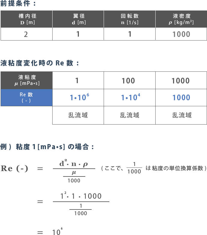
The basic specifications of the R1 and R2 tanks, each of which has a liquid capacity of 10 m3, are as follows: As you know, the operating viscosities of R1 and R2 are 1 mPa・s and 100 mPa・s, respectively. Let's put them into the above equation. Then...
As shown in blue in the table below, when the viscosity is 1, 100, and 1,000 mPa・s, the Reynolds number is 106, 104, 1,000, respectively.
Next, let’s take a look at the Np-Re curve in Figure 1 with these Reynolds numbers in mind.
Here, Np is a dimensionless number, which indicated the power characteristics of the mixing vessel taking the the impeller, vessel shape, and internals into consideration. From the fact that the Reynolds number is larger than 1,000 when the viscosity is 1,000 mPa・s or lower, you can see that the flow in the mixing vessel is in the turbulent flow region. Also, from the fact that the graph of Np is horizontal in the turbulent flow region in Figure 1, you can recognize the rule that the power number Np is constant in the turbulent flow region.
These are the reasons why Max judged that a liquid viscosity difference of 1 to several hundred mPa・s has no influence on the power. Furthermore, from the fact that viscosity change does not affect the power, he judged that the change of apparent viscosity of Non-Newtonian fluids does not matter in this region.
Principle 2: The power is affected by the internals in the turbulent flow region.
Regardless of the fact that a liquid viscosity difference of 1 to several hundred mPa・s has no influence on the power, the power was significantly different between the R1 and R2 tanks. It was due to the rule that the power is greatly affected by the internals in the turbulent flow region. In Figure 1, you can see that the graph converges into a single curve in the laminar flow region since the flow is dominated by viscous force and therefore the internals do not affect the power, but in the turbulent flow region, the power number varies depending on the baffle conditions. Max kept this graph in his mind, and therefore was able to imagine such an influence immediately.
Principle 3: The power P is proportional to the first power of the density and the cube of the rotation speed of the impeller in the turbulent flow region.
Finally, let’s think about how much the rotation speed of the impeller can be increased. The influential factors of the power P (kW) vary as follows depending on the type of the flow.

The exponent of the rotation speed n is different between the laminar flow region and turbulent flow region (with baffles). Remember that the power is affected by the square of the rotation speed in the laminar flow region, and by the cube, in the turbulent flow region (with baffles). Also remember the risk that easily and greatly changing the rotation speed is highly likely to cause motor trip due to overload or the like.
How was this session? By understanding the outline of the Three Principles of Mixing and the meaning of the Np-Re curve together, you can evaluate and judge the flow in an actual mixing vessel taking the power characteristics into consideration, like Max. Then, a wider world will come into view.
We believe you can also learn a lot if you once investigate in which region of the Np-Re curve mixing vessels are running in your plant. Do your best to become an engineer who can answer questions and make decisions on the spot!
-
Mixing Course
Beginner
course -
- Introduction Basic terms of mixing
- Course 1 Basics of basics: Three points to understand mixing
- Course 2 Examples of the purposes of mixing
- Course 3 Viscosity is the unit of stickiness
- Course 4 Consider a mixing vessel as a huge viscometer
- Course 5 Can you see the flow from power change? (Part 1)
- Course 6 Can you see the flow from power change? (Part 2)
- Course 7 Learn the essence of the mixing Reynolds number
- Course 8 Basics of basics of scaling up
- Course 9 Basics of scaling up
- Course 10 What is heat transfer performance in a mixing vessel?
- Course 11 What is film heat transfer coefficient , hi?
- Course 12 Mixing course review
-
Mixing Course
Practical
course -
- Introduction Mixing course SEASON II
- Course 1 Immediately determine the basic specifications of the mixing vessel using three pieces of information: operating liquid volume, viscosity and density.
- Course 2 Find a plan to improve the productivity of the mixing tank on the existing production line! (Part 1)