 Course 11
What is film heat transfer coefficient , hi?
Course 11
What is film heat transfer coefficient , hi?
In the previous session, we explained the need to be aware of the resistance ratio for the five factors that make up the overall heat transfer coefficient, U value in terms of heat transfer performance in a mixing vessel.
Now, we will discuss one of the factor in U values, the film heat transfer coefficient (inside of mixing vessel), hi, which is significantly affected by the mixing method and liquids to be mixed.
For turbulent mixing in a tens of liters testing apparatus, the proportion occupied by heat transfer resistance, such as metal resistance of vessel wall, other than hi tends to be large, so it is less likely that mixing method significantly affects the heat transfer performance U value. Furthermore, in a small sizes, since heat transfer area per unit volume (A/V) is sufficient, there are enough capacity on removal of reaction heat or the like.
However, for large-scale mixing vessels of 10 m3 or more, hi is more likely to be rate limiting for heat transfer as A/V decreases.
This is why the role of mixing impellers with high heat transfer performance (=higher hi is available) for commercial scale facilities is important.
In particular, for mixing polymers with properties of high non-Newtonian fluids, care should be taken because there is a risk of hi decrease significantly unless suitable mixing impellers are used capable of forming a strong circulating flow in the entire vessel.
Case study:
At a pilot plant facility in a chemical company
Well, here is a trial production experiment building of a certain chemical company again. Current recipe of the prototype is, a low viscosity monomer raw material becomes a high viscosity polymer (about 20 Pa·s) in the final stage. Then it will be cooled from 150 °C to 80 °C and be transferred to the following processes.

Max
This product generates a large heat reaction during the polymerization reaction. Is it OK?

Dr.Nano
We can manage to remove the heat during the liquid is still low viscosity at the beginning.
The second half seems to be difficult as the viscosity is increased. Also, we have an issue because the cooling time is long for high-viscosity liquids.

I see.
The non-Newtonian property increases as the viscosity increases, so the apparent viscosity around impeller and near vessel wall is significantly different, which may also be the cause of the decreasing heat transfer.

Right! It is almost the final stage. It's the high-viscosity region. Let's check on the mixing condition.

Ok! I'm very excited to see the flow condition of the actual operation at site!
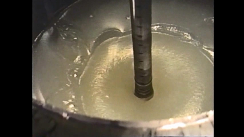
They checked mixing condition of the viscosity increased polymer solution through the observation glass. The photos and video clip are below. (For the sake of convenience, simulant mixing condition from our 200 litter testing apparatus is posted.) Check it out.
< Mixing Conditions >
Impeller types:
3 stages pitched blade paddle
Fluid types:
non-Newtonian fluid (CMC aqueous solutions, viscosity: 20 Pa·s)
Diameter of the vessel: 600 mm
Fluid volume: 130 L
< Mixing Conditions >
| Impeller types | : 3 stages pitched blade paddle |
| Fluid types | : non-Newtonian fluid (CMC aqueous solutions, viscosity: 20 Pa·s) |
| Diameter of the vessel | : 600 mm |
| Fluid volume | : 130 L |
Photo 1: Flow on a liquid surface
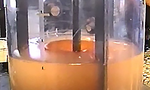
Photo 2: Coloring agent only diffuses near impellers

Movie 1: Fluid stopping phenomenon of non-Newtonian fluid

Wow! What is this? It was well mixed when the viscosity was low. What on earth happened?
This is the fluid stopping phenomenon of non-Newtonian fluid! This is the first time I saw it.

What? What is the fluid stopping phenomenon?

It is a specific phenomenon to high-viscosity non-Newtonian fluids. The apparent viscosity decreases because of the high shear rate around mixing impellers, so a strong circulating flow can be formed, but the circulation flow rapidly decreases near the wall of the vessel, away from the impellers, and the fluid becomes jelly-like.
I have heard that this phenomenon can occur under mixing conditions with small-size impellers, because a circulation flow can only be generated near impellers.

How can we calculate hi under such flow conditions?
There is no flow running on the wall. It is just jiggling.
I learned the boundary-layer thickness at the vessel inner wall surface represents film resistance in terms of convective heat transfer, but there is no convection flow!
Hi everyone, how was it? As you can see, the two people are shocked to see the fluid stopping phenomenon of non-Newtonian fluids for the first time.
The photos and video clip above show test examples with 3 stages pitched paddle impellers in CMC solutions of about 20 Pa·s.
For example, when cooking curry or stew, you may want to scrape the bottom or sides of the pod with a ladle. That is because the target liquid is close to the fluid as shown.
As with miso soup and stew, the tools for mixing are different. Similarly, it is very important to select the best mixing impellers depending on the objects and operation methods. It is extremely difficult to estimate mixing times and heat transfer coefficients for a mixing vessel when the overall circulation flow has not yet been formed.
The example we introduced here may be a little extreme, but in an actual industrial setting, situations similar to these phenomena sometimes occur during manufacturing.
With this in mind, look at the equation for calculating film heat transfer coefficients. The basic formula is shown in Equation 1 below.
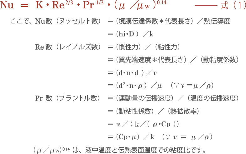
Other symbols are as follows:

Oh No! Nusselt number, Prandtl number, again, you see words that may be unfamiliar. We will leave the detailed explanation to technical books. Understand the meaning of each dimensionless number in the following way.
What is the Nusselt number (Nu)?:
It is the ratio of convection heat transfer to fluid conduction heat transfer.
In case of mixing operation, it is the ratio of the amount of heat transferred by forced convection with impellers to the amount of heat transferred by heat conduction of the fluid itself.
Therefore, Nu = 1 is a completely stationary fluid (heat is transferred only by heat conduction).
Note that characteristic length D is included as expressed for Np values and Re number. Therefore, when geometric similarity conditions cannot be kept, we cannot discuss the magnitude of heat transfer performance depending on the Nusselt number, similar to the Np value.
In addition, the inner diameter D is usually used as characteristic length for jacket heat transfer in the mixing vessel.
What is the Prandtl number (Pr)?:
It indicates the ratio of thickness of velocity boundary layer to thickness of temperature boundary layer.
Well, it is difficult. Considering jacket heat transfer in a mixing vessel, it can be explained as follows.
Thickness of velocity boundary layer means the radial dimension from the vessel inner wall surface where the flow velocity is zero to bulk flow velocity in the vessel.
Thickness of temperature boundary layer is defined as the radial dimension from the vessel wall to a position where the temperature has reached to a stable temperature.
Therefore, it indicates that the smaller the Prandtl number, the faster the heat diffuses compared to the fluid momentum.
Prandtl number is a dimensionless number determined only by physical property (viscosity, specific heat, and thermal conductivity). Try to memorize the approximate value for typical ones.
Examples at a temperature of 20 °C are as follows: Air is 0.71, Water is about 7.1, and Spindle Oil is about 168. As the fluid becomes sticky (high viscosity), the Prandtl number steadily increases.
Now, from basic equation (1), the relationship with each factor of the film heat transfer coefficient hi of a mixing vessel is as follows:

Therefore, the contribution ratio for each factor is as follows:

With equation 3, we will explain some important points when considering the film heat transfer coefficient hi of a mixing vessel.
Point 1
Although hi increases in proportion to only 2/3th power of the rotating speed, mixing power increases in proportion to the third power of rotating speed. (Turbulent flow zone). Therefore, a design concept of adjusting insufficient heat transfer performance with increase rotating speed of impeller which selected without sufficient consideration is not realistic. In other words, mixing power consumption increases 3.4 times at 1.5 times the rotating speed increase, but hi increases only 1.3 times. Furthermore, with hi of 50% of U value, the U value improvement rate is only 1.13 times.
Point 2
In the heat transfer calculation, the factor with the largest change ratio is viscosity. For example, low viscosity liquid like water increases about 1,000 to 10,000 times. Since hi decreases with the -1/3 power of the viscosity, hi is decreased to 1/10 with a 1,000-fold increase in the viscosity and 1/20 with a 10,000-fold increase.
Point 3
Thermal conductivity k affects hi with 2/3 power. Since thermal conductivity of polymer solutions, oils, and so on is only about 1/5 of the water-based fluids, hi drops to over 30% with 0.2 to the power of 2/3. Also, Specific Heat Cp of polymer solutions is about one-half of that of water-based fluids, so hi drops to about 80% with 0.5 to the power of 1/3.
Consider hi while focusing on viscosity. Remember that in polymer solutions, hi decreases compared to water-based fluid in terms of thermal conductivity and specific heat. Care should be taken regarding the difference in thermal conductivity and specific heat because the fluid of the jacket side and coil side greatly affects the outside film heat transfer coefficients (ho) depending on whether it is water-based or thermal-oil based.
That is all for this session. We introduced important design points regarding film heat transfer coefficients for inside of a vessel (hi), which can be critical to heat transfer while mixing.
In general, hi calculation formula is organized as a function of the Reynolds number and the Prandtl number; however, circulating flow reaching the overall area of a vessel must be formed by mixing impellers.
However, for highly viscous liquids with high non-Newtonian properties, hi suddenly decreases in some cases due to the fluid stopping phenomenon. In such a condition, it is also necessary to consider other options, such as special large impellers and complex, multi-shaft mixers.
We will summarize the mixing course (beginners' course) in the next session. Also, we will review what we have discussed over the past year.
Not the overall heat transfer coefficients, U values, it will be about the overall summary of mixing course!
A variety of unit operations, such as reaction, dissolution, heat transfer, and extraction, are occurring inside a mixing vessel. What is rate limiting in the mixing device you are studying? It may be the same as identifying the maximum resistance factor of the overall heat transfer coefficient.
The ability to notice the most important thing is needed for a true engineer!
-
Mixing Course
Beginner
course -
- Introduction Basic terms of mixing
- Course 1 Basics of basics: Three points to understand mixing
- Course 2 Examples of the purposes of mixing
- Course 3 Viscosity is the unit of stickiness
- Course 4 Consider a mixing vessel as a huge viscometer
- Course 5 Can you see the flow from power change? (Part 1)
- Course 6 Can you see the flow from power change? (Part 2)
- Course 7 Learn the essence of the mixing Reynolds number
- Course 8 Basics of basics of scaling up
- Course 9 Basics of scaling up
- Course 10 What is heat transfer performance in a mixing vessel?
- Course 11 What is film heat transfer coefficient , hi?
- Course 12 Mixing course review
-
Mixing Course
Practical
course -
- Introduction Mixing course SEASON II
- Course 1 Immediately determine the basic specifications of the mixing vessel using three pieces of information: operating liquid volume, viscosity and density.
- Course 2 Find a plan to improve the productivity of the mixing tank on the existing production line! (Part 1)