 Course 5
Can you see the flow from power change? (Part 1)
Course 5
Can you see the flow from power change? (Part 1)
In the previous session, we said that a mixing vessel is a huge viscometer and that you can obtain much information about the liquid in the vessel, such as whether the liquid is Newtonian or Non-Newtonian, whether the flow is turbulent or laminar, and whether there are baffle plates or not, from the power change during operation.
In this session, let us assume a production site in a chemical plant and give an explanation so that you understand the key points more practically.
Case study:
In a chemical plant
In this chemical plant, threr are recently installed two mixing vessels named R1 and R2 tanks. Both tanks have the same liquid capacity of 10m3, same vessel size, same impeller size, same motor capacity, and even the same rotation speed. However, the operating viscosity of R1 is 1 mPa・s, which is almost the same as that of water, whereas R2 has an operating viscosity of 100 mPa・s, which is 100 times that of R1.
At these tanks, two of the staff are talking. The earnest-looking young man wearing glasses is Max. He is in his third year as a chemical engineer. Max, who majored in mixing technology in college, is being asked something by his senior, Dr.Nano, who is an experienced manufacturing staff member in his 10th year.

Dr.Nano
Commercial operation finally started last month.
Both tanks are going well. Now we can breathe easier.

Max
Introduction of these tanks was my first job.
I really feel relieved now.

At present, we are somehow managing to manufacture the product, but there's two things I want to consult with you.
I want to hear your opinion.

I see. What's the problem?

One is about the motor consumption power during operation, and the other is that I want to make the rotation speed a little bit higher.
First, about the motor consumption power, in spite of running under the same conditions except the viscosity, the operating power of R2 is lower than that of R1 even though the viscosity of R2 is no less than 100 times that of R1.
Is it caused by motor failure, or because of measuring instrument failure? In either case, I want to ascertain the cause and fix it early. What do you think?
Also, I am going to try increasing the rotation speed of the impeller of R2 to 1.5 times tomorrow since the operating motor power of R2 is still around 40% of the rated power and there is plenty of room to spare.
I think if we increase the rotation speed, the apparent viscosity, and consequently the load will decrease since the product is a Non-Newtonian fluid.
If there is no problem, I will give directions to site workers right away.
Well, if you were Max, how would you answer?
Dr.Nano takes care of various equipment throughout the plant, and therefore does not know much about mixing technology. In addition, Dr.Nano is always very busy, so that it is hard to say “I’m sorry, I simulate it on a PC and I will e-mail you tomorrow.”
We suppose such a situation is not unusual for you, too.
This question may seem to be difficult at first glance, but as long as you know simple rules on the flow in a mixing vessel, you can answer it immediately on the spot.
Now, let 's take a look at the model answer with this figure of a mixing vessel in mind.
Be an engineer who can answer questions and make decisions on the spot!
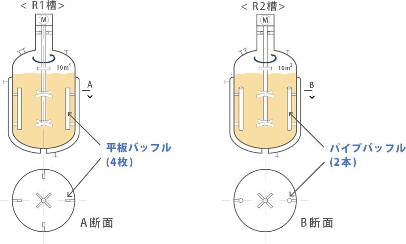
Figure 1. Shape of baffles in a mixing vessel

You don't have to worry about the motor consumption power.
The power displayed on the monitor is correct. The difference in power is due to the difference of baffles, or baffle plates, installed inside the mixing vessel.
The R1 tank is for low viscosity fluids, and therefore equipped with four flat plate baffles, but R2 is for medium viscosity fluids, and therefore has two pipe baffles so as to reduce stagnation and adhesion on the back of the baffles. I think the reason why the consumption power is different is because the power number differs due to this difference in the baffle conditions.
What? A difference in the baffle conditions?
The site workers including me only cared about the appearance of the tanks, and therefore misunderstood that the two tanks are identical.
In case of 10 m3 scale mixing vessels, as long as the viscosity is in the range of 1 to 100 mPa・s, the mixing power is proportional to the first power of the density regardless of the viscosity. Because mixing power is dominated by inertia force in such a turbulent flow region with baffles condition. Consequently, the power does not increase even with 100 times the viscosity.

I see. This is what the phrase “the interaction between the impeller, vessel, and internals (baffles and others) determines the flow in the mixing vessel” means. Thank you.
Then, what do you think about increasing the rotation speed?
If you increase the rotation speed to 1.5 times, it will cause overloaded operation significantly exceeding the rated load of the motor, and consequently the motor is stopped.
Under the current operating conditions, the power is proportional to the first power of the density and the cube of the rotation speed. Therefore, if you increase the rotation speed to 1.5 times, the power increases to roughly 3.4 times, that is, the cube of 1.5 times.

I got it. A slight change of the rotation speed significantly changes the power, doesn't it?
I will be careful from now on.

If you want to increase the loading condition from the current 40% to 80%, I recommend increasing the rotation speed to around 1.2 times.
In addition, you don’t have to worry about overloading at all even with Non-Newtonian fluids because the power is not affected by viscosity change in the inertia force-dominated region. I think it is no problem as long as 1.2 times the rotation speed is within the range of the manufacturer’s design.
What do you think? Max is doing pretty good job, isn’t he?
His explanation may be a little bit difficult because unfamiliar words such as “baffles”, “turbulent flow”, and “inertia force-dominated” suddenly appear.
However, what he said is only a basic knowledge of mixing, which you can easily understand as long as you understand the meaning of the Np-Re (Power number vs Reynolds number) curve, a classical graph of mixing.
Figure 2. Np-Re curve
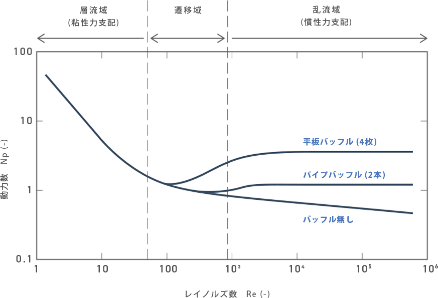
Understanding these rules, you can imagine the flow in the mixing vessel in operation from the degree of power change when the rotation speed is changed.
This is the first great step to become “an engineer who can answer questions and make judgments on the spot.”
Then, let’s start with knowing the rules of flow during mixing in the next session, "Can you see the flow from power change? (Part 2)". We will explain how to reach the model answer using simple graphs and equations, in an easy-to-understand manner. See you in the next session!
Let's be able to image the flow in a mixing vessel from power change.
-
Mixing Course
Beginner
course -
- Introduction Basic terms of mixing
- Course 1 Basics of basics: Three points to understand mixing
- Course 2 Examples of the purposes of mixing
- Course 3 Viscosity is the unit of stickiness
- Course 4 Consider a mixing vessel as a huge viscometer
- Course 5 Can you see the flow from power change? (Part 1)
- Course 6 Can you see the flow from power change? (Part 2)
- Course 7 Learn the essence of the mixing Reynolds number
- Course 8 Basics of basics of scaling up
- Course 9 Basics of scaling up
- Course 10 What is heat transfer performance in a mixing vessel?
- Course 11 What is film heat transfer coefficient , hi?
- Course 12 Mixing course review
-
Mixing Course
Practical
course -
- Introduction Mixing course SEASON II
- Course 1 Immediately determine the basic specifications of the mixing vessel using three pieces of information: operating liquid volume, viscosity and density.
- Course 2 Find a plan to improve the productivity of the mixing tank on the existing production line! (Part 1)