 Course 10
What is heat transfer performance in a mixing vessel?
Course 10
What is heat transfer performance in a mixing vessel?
In the previous session, we explained that the heat transfer area per unit volume of liquid decreases when scaling up with geometric similarities condition, and it becomes disadvantageous in terms of heat transfer performance.
Actually, heat transfer performance in mixing vessels have many aspects that cannot be explained only by heat transfer area.
This time, we will discuss: "What is the heat transfer performance in mixing vessels?"
Case study:
At a pilot plant facility in a chemical company
Well, here is a trial production experiment building of a certain chemical company. Many pilot devices of about 10 L to 200 L are installed in this building.
Max and his senior, Dr. Nano from the manufacturing department, are discussing something.

Dr.Nano
Today, we will be making a prototype in a 100 L pilot vessel (design temperature: 150 °C, design pressure: 0.2 MPaG, maximum rotation speed: 200 rpm). Do you think the temperature and pressure are suitable for that?

Max
Yes, we will operate at 100 °C and a pressure of 0.1 MPaG, so it will be OK. And for the rotating speed of about 100 rpm, there will be a sufficient margin as well.

There is no heat transfer coil inside the vessel. So, heat transfer will be only depend on the outside jacket. There is no issue with heat transfer performance, isn't it ? Are you sure the reaction heat can be removed without problems?

We have calculated the heat transfer coefficient at the set rotation speed using a formula from the Chemical Engineering Handbook, and there is approx. 30% margin. If it is insufficient, we can increase the rotation speed.

Really? Is it possible to increase heat transfer performance by increasing rotation speed? According to my experience at the pilot vessel, heating or cooling time does not changed so much, even in changed the rotation speed condition.

No, I do not think so. I learned that the heat transfer coefficient is proportional to Re2/3 under low viscosity turbulent conditions.
Since Reynolds number is proportional to rotation speed (n), the heat transfer coefficient should increase at n2/3.

Really ? I am a bit worried about that.

I think you worry too much. Mixing in Turbulent mixing of low viscosity liquid is a piece of cake. Why not measure changes in heat transfer performance by increasing the rotation speed at prototyping?
Mr. Ueda (who has fewer lines this time), our Sales Manager, is passing by and is yelling something.

Mr. Ueda
Guys, stop fooling around! Hurry up and make a new sample, right away!
Dr. Nano does not seem to understand things well, considering past experiences, but Max looks very confident because he has studied it previously.
What do you think about their conversation?
What is heat transfer performance in a mixing vessel?
(=Amount of heat exchanged per unit time!)
In session 1 of this course we told "Let's understand the purpose (WHAT) of mixing operation! Mixing itself is a means, and the purpose is different!"
Now, the purpose of mixing is heat transfer.
So, what is heat transfer performance in a mixing vessel and how should it be expressed?
Because it is described as heat transfer = transferring heat, is a magnitude of heat transferred? Yes, that is correct. Similar to tubular type heat exchangers, the heat transfer performance (capacity) in mixing vessels is expressed in terms of exchange heat quantity per unit time (W or Kcal/hr).
As shown in Equation 1, the heat exchange quantity is determined by multiplying Heat transfer area A(m2), Overall heat transfer coefficient U(W/m2K), and Temperature difference ⊿T(K).

Normally, in order to increase exchange heat quantities Q, it is effective to increase heat transfer area A with a jacket or multiple winding internal coils, or increase temperature difference ⊿T between process liquid and jacket/coil-side liquid. These two factors directly influence exchange heat proportionally, so, making them very effective.
However, multiple winding internal coils could be a trade-off with issues such as adhesion due to stagnant region in a vessel. Also, the temperature difference cannot be set so large because of induces problems, such as fatigue fracture of the jacket-shell welding part and excess heating of the process fluid. So, it should be decided within a commonsense range corresponding to the size of the vessel.
Basically, the heat transfer area and applicable temperature difference are not directly influenced by mixing conditions or impeller type, of course. But, it is indirectly affected in some cases. For example, with a medium viscosity fluid of several thousand mPa·s, only single winding internal coil is allowed with paddles impeller to avoid stagnation and adhesion problems. But, in case of MAXBLEND with high mixing performance, it may be operational with less stagnation even with double windings coils.
What is the overall heat transfer coefficient U?
(=Summary of each heat transfer resistances of 5 layers!)
Well, the issue is the overall heat transfer coefficient, or U value. Don't you think the name itself is not quite clear-overall heat transfer coefficient ? The coefficient that sums up heat transfer sounds somewhat bossy. However, by accurately understanding this U value, you will be able to grasp the meaning of heat transfer performance in the mixing vessel.
Now, we will explain how the U value is calculated. It is expressed using Equation 2.
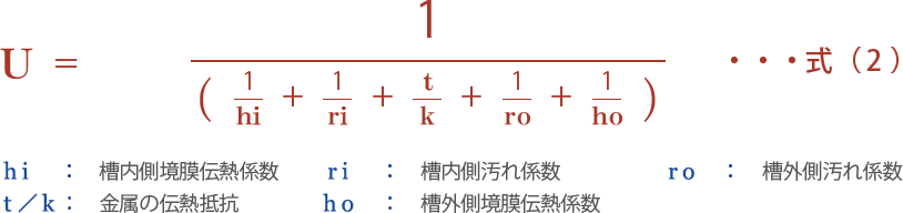
As expected, it is Mr. Overall. The five factors are summarized overall. Here, Fig. 1 shows the location of each factor. In other words, when heat is transferred, these five factors serve as resistance at each location. The reciprocal number (1/hi, and so on) of each heat transfer coefficient is the heat transfer resistance, the sum of each resistance represents the overall heat transfer resistance 1/U, and the reciprocal thereof is called the overall heat transfer coefficient U.
Figure 1. Heat transfer resistance of each part
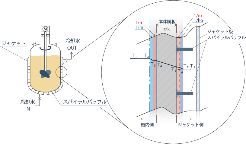
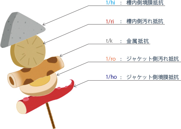
Figure 2. True identity of the overall heat transfer resistance
The important thing when discussing the heat transfer coefficient is, you should be well aware that it is about the overall U value, or one of the five factors of a U value, such as the inner film heat transfer coefficient, hi.
Let us explain once again with delicious food as an example. Suppose two people who like Oden are discussing its taste. (Oden; a Japanese traditional one-pot dish consisting of several ingredients such as fishcakes, vegetables like daikon radish and others stewed in dashi broth). They may be talking about a variety of Oden ingredients skewered together, or focusing the taste of daikon radish among Oden ingredients. If the point of reference is not shared, the argument will gradually differs.
Back to the conversation of the two people at the beginning, the difference in understanding of two people has occurred in same way. What Max calculated using the handbook was the inner film heat transfer coefficient hi. Dr. Nano said that there was no influence of temperature changes on small devices even if the rotational speed was changed, which probably indicated that the overall heat transfer coefficient had not changed significantly.
Moreover, as shown in Fig. 2, when the total height of one skewer of Oden is defined as the overall heat transfer resistance 1/U, the ratio of the height of each ingredient therein varies greatly depending on the liquid physical properties and mixing conditions. Therefore, when evaluating the heat transfer performance of a mixing vessel, It's very important to figure out identify which the heat transfer resistance is the rate limiting among the overall U values (which ingredient is larger on one skewer). Then, consider measures to make the large resistance (ingredients) smaller.
Fig. 3 shows the resistance ratio of five factors of the U value when changing the liquid viscosity in the vessel of capacity 100 L. Looking at this, you can see that the resistance ratio of 5 factors of the U value changes greatly depending on the viscosity of the process liquid.
Figure 3. Changes in resistance ratio of five factors of a U value in a 100 litter vessel
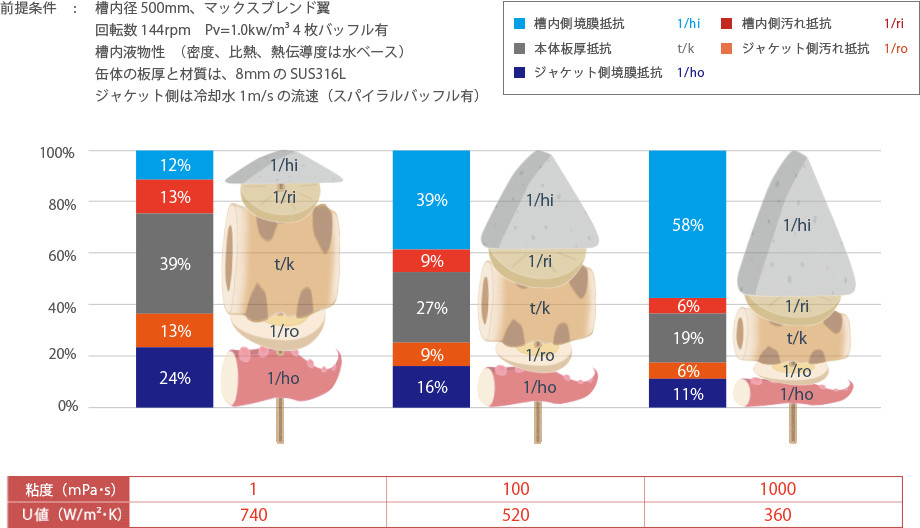
The U value of the mixing vessel varies depending on conditions, and the degree of influence of each heat transfer resistance factor also changes. Therefore, the largest factor in heat transfer resistances which becomes the rate-determining within the U value may also change.
It is necessary to estimate the composition ratio of these five factors for each mixing vessel and operating condition. The U value cannot be increased unless measures are taken to decrease the resistance of the major factors.
In a small vessel about 100 litter at mixing of low viscosity liquids, since the ratio of vessel wall metallic resistance (Chikuwa) is large, it should be expected that increasing the rotating speed and reducing the inside vessel film heat transfer resistance (Konnyaku) will not have much effect on improving the U value.
In that sense, we can say that this time Dr. Nano's view based on his experience did predict the actual phenomenon of low viscosity liquids in small testing vessels.
In addition, if you look at these five factors individually, you will find that all but hi are unaffected by mixing. This is because these factors are determined by the vessel materials, plate thickness, degree of fouling due to such as adhesion and corrosion, fluid characteristics and flow rate and flow-path structure in jacket, and so on.
The following are approximate common sense of practical engineers.
| ri | Heat transfer resistance due to adhesion, scaling etc. on the inner surface of a vessel. Generally, It can be estimated approximately 6,000 (W/m2・K). |
|---|---|
| ro | Heat transfer resistance due to adhesion, corrosion, and others on the outer surface (jacket side) of a vessel. Similarly, it is approximately 6,000 (W/m2・K) for a new vessel. |
| t/k | The heat transfer resistance determined by the plate thickness and the thermal conductivity of the metal. Note that the thermal conductivity of stainless steel is only 1/3 of carbon steel plate (three times worse). In other words, the 10mm stainless steel plate has same heat transfer resistance as 30mm carbon steel plate. Generally, clad materials (3 mm stainless steel cladding on carbon steel base plate) are usually applied for large vessels. On the other hand, solid stainless steel is applied for small pilot vessels. So, the metal resistance tends to increase due to the difference in material compared to large vessels. |
| ho | Jacket side film heat transfer coefficient. In a condition of water cooling at a flow rate of about 1 m/s with spiral baffles, ho will be approximately 1,800 (W/m2・K). For small vessels around 100 litter, generally spiral baffle is not provided in jacket. In such a case you need to pay attention that the flow rate decreased dramatically, worsening the ho. |
The value of the above four factors can be roughly calculated with a calculator regardless of mixing conditions. Then, if the rough value for these four factors is in your mind, the ratio of hi to the U value can be estimated from the calculation result of the remaining vessel inner film heat transfer coefficient hi. And, you can judge whether the improvement of mixing condition is effective or not.
If you can picture this ratio by looking at the vessel size, process fluid viscosity, vessel material, and so on, you are already a top engineer!
-
Mixing Course
Beginner
course -
- Introduction Basic terms of mixing
- Course 1 Basics of basics: Three points to understand mixing
- Course 2 Examples of the purposes of mixing
- Course 3 Viscosity is the unit of stickiness
- Course 4 Consider a mixing vessel as a huge viscometer
- Course 5 Can you see the flow from power change? (Part 1)
- Course 6 Can you see the flow from power change? (Part 2)
- Course 7 Learn the essence of the mixing Reynolds number
- Course 8 Basics of basics of scaling up
- Course 9 Basics of scaling up
- Course 10 What is heat transfer performance in a mixing vessel?
- Course 11 What is film heat transfer coefficient , hi?
- Course 12 Mixing course review
-
Mixing Course
Practical
course -
- Introduction Mixing course SEASON II
- Course 1 Immediately determine the basic specifications of the mixing vessel using three pieces of information: operating liquid volume, viscosity and density.
- Course 2 Find a plan to improve the productivity of the mixing tank on the existing production line! (Part 1)