 Introduction
Basic terms of mixing
Introduction
Basic terms of mixing
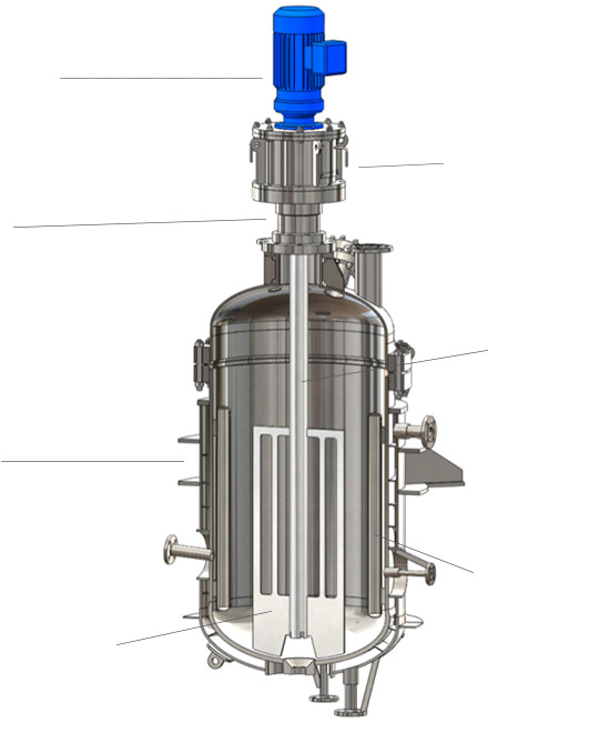
Structure of mixing equipment
The structure of mixing equipment is relatively simple.
A wide variety of purposes can be achieved by how suitably combine components of various types, sizes, arrangements, and so on.
And, it is not too much to say that the quality of the final product is decided by the quality of mixing operation and equipment.
In this session, we introduce the general structure of mixing equipment and basic terms of mixing, which are necessary to understand the basics of mixing.
Impeller
Is the most important component of mixing equipment.
The impeller converts the rotational energy from the motor into two conflicting actions: the discharge action, which forms a circulation flow throughout the vessel, and the shear action, which generates shear force locally.
Therefore, when you select the impeller, though it is roughly decided by the viscosity of the raw material, it is extremely important to consider which action to give priority and how they are to be balanced to achieve your intended mixing.
There are a wide variety of impellers in the industry, but the major ones are as follows:
Major impeller type
| For Low viscosity | Propeller impeller | 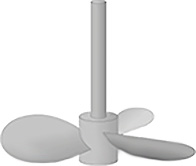 |
Propeller impeller This is the most common impeller.This is suitable for low to medium viscosity liquids, and energetically advantageous when suspending solid particles in a low viscosity liquid since an axial flow is formed. |
|---|---|---|---|
| Disk turbine impeller | 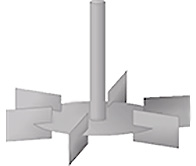 |
Disk turbine impeller This impeller has a shape of a disk attached with blades.This is suitable for low to medium viscosity fluids, gases, and liquids. Though it requires high consumption power, it is best characterized by its ability to generate high shear force, as well as the discharge ability and wide application range. |
|
| Pitched paddle impeller | 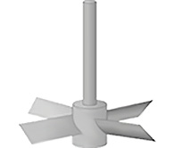 |
Pitched paddle impeller This impeller has blades each in a shape similar to an oar of a small boat.This is suitable for low to medium viscosity fluids, and widely used in industries. It is usually used in large scale and at low speed, and those with baffles can generate a strong turbulent flow. |
|
| For High viscosity | Anchor impeller | 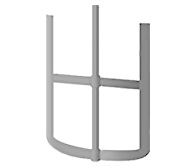 |
Anchor impeller This impeller has a shape similar to an anchor of a ship.This is suitable for high viscosity fluids, and advantageous when the wall boundary layer is disturbed and when solids adhere to the wall. However, it hardly generates an axial flow, and therefore not suitable for mixing. |
| Helical-ribbon impeller | 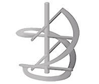 |
Helical-ribbon impeller This is a typical impeller for high viscosity fluids.While having the same features as the anchor impeller, it also generates an axial flow by its inclined blades. |
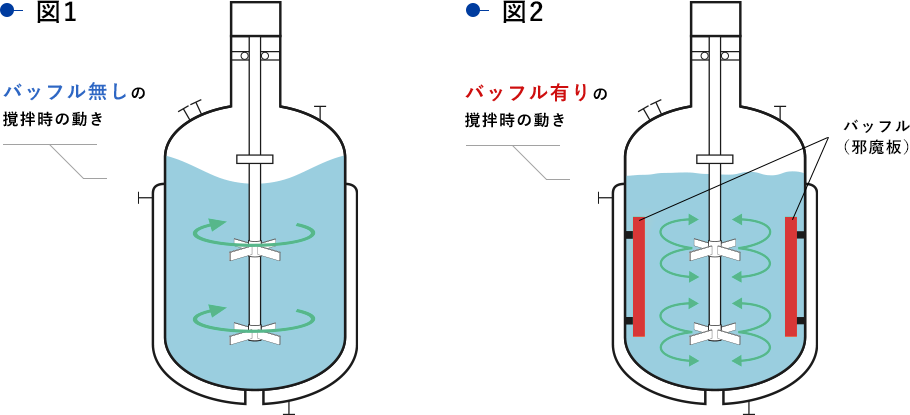
Baffle
In general, two to eight flat plates or cylindrical pipes are equally positioned at inner wall of a mixing vessel as baffles.
Without baffles condition, rotating an impeller generates only a lateral circulation flow (called “co-rotation”) as shown in Figure 1.
With baffles condition, however, also a vertical flow is generated, disturbing the lateral flow, as shown in Figure 2.
Therefore, baffles are regarded as one of the most simple way to enhance the mixing performance. Especially when mixing a low viscosity liquid, usually baffles are applied. Meanwhile, the mixing performance depends on the arrangement, number, and length of baffles, so that it is necessary to optimize them according to the purpose and conditions.
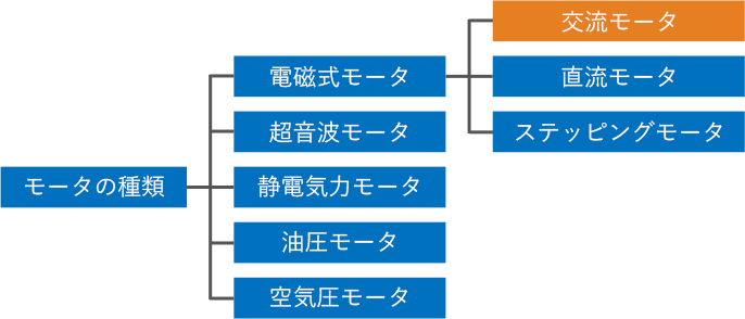
Motor
A motor is the power source for rotating mixing impeller.
Although there are various kinds of motors, AC motors are commonly used in mixing devices. In addition, motor ratings have been standardized by JIS C 4210 in Japan.
Motor Selection
(Selection of Motor Capacity)
It is necessary to decide the mixing power required to achieve the purpose of mixing operation at first, and optimum motor power capacity will be decided in consideration of some margin and mechanical power loss caused by speed reducer, etc.
However, excessive power margin leads to an increase in initial cost as well as an increase in running cost.
In addition, not only for the motor capacity, environmental condition need to be taken into the account to choose proper specification suitable with, for example, power supply (voltage , frequency), hazardous area classification (explosion-proof structure), insulation class, etc.
※ Commonly used in
mixing devices
Speed Reducer
A speed reducer is a device to decrease rotational speed using a gear or similar, on the other hand it enables to increase rotating force (torque) larger. For example, in case of the same motor capacity, if you reduce the rotational speed by 50%, the torque will double.
It is necessary to select a proper speed reducer suitable for desired rotation speed for the purpose of mixing, among a variety of speed reducer types supplied by many different manufacturers.
Speed reducers supplied by Sumitomo Heavy Industries, Ltd. are commonly used in agitators. Following shows features of the typical speed reducers.
* Cyclo®Drive and Paramax® Drive are registered trademarks of Sumitomo Heavy Industries, Ltd.
Typical Speed Reducer
Cyclo®Drive
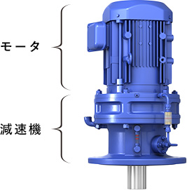
- Gear type
- Agitation torque: low to medium
Paramax® Drive
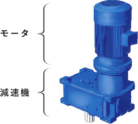
- Gear type
- Agitation torque: medium to large
- Available for a special reduction ratio by changing the number of teeth on a gear.
Speed Variator
A speed variator is a device that provides variable rotation speed. The speed reducers described above are used to decrease the rotation speed of the motor with a fixed constant ratio (reduction ratio), whereas the speed variator is a device that can adjust the rotation speed.
For agitator application, Electrical or mechanical types are commonly used as speed variator systems. A typical electric transmission is an inverter, and a typical mechanical type is Beier Variator®.
Necessity of speed variator systems and selection
Speed variator system is recommend to apply in the following cases:
(1) Viscosity varies during operation of a mixing device
(2) Multi-products production with a single agitator
(3) Experimental purpose in R&D phases to find optimum mixing speeds
Following table shows comparison of two speed variator systems. In recent years, Variable Frequency Drives (VFD) trend to be selected more often.
Typical Speed Variator Systems and their Characteristics
Variable Frequency Drives (VFD)
- Electrical control
- Changing by varying motor input frequency and voltage. (Motor rotating speed is changed)
- Gear ratio is usually 1:10.
- Free from mechanical power loss
- Light weight and compact
- Some electrical work may be required.
- Constant torque regardless of rotational speed.
Beier Variator®
- Mechanical control
- Changing by reduction ratio. (Motor rotating speed is constant)
- Gear ratio is usually 1:4
- Higher mechanical power loss
- Large and heavy
- No electrical work required
- High torque available even in low speed range (constant output)
* Beier Variator® is a registered trademark of Sumitomo Heavy Industries, Ltd.
Shaft Seal
A shaft seal is a leakage control device that prevents liquids and gases leakage out from a mixing vessel along the rotating shaft.
The shaft seal requires both high airtightness to seal the interior of the vessel and functionality to stably transmit rotation. So, it's very important component to maintain the overall performance, safety and economic efficiency of agitators.
The shaft seal type should be selected based on the operating conditions such as pressure, temperature, properties of liquids to be used, safety hazards, corrosiveness, rotation speed, presence or absence of solids and others.
Although many types of mechanical seals are available in the industry, those commonly used in mixing devices are shown below.
Typical Shaft Seal Systems and their Characteristics
| Mechanical Seal | Characteristics |
|---|---|
| Single Mechanical Seal (Dry Seal) |
|
| Double Mechanical Seal |
|
| Stuffing box with Gland Packing |
|
| Oil Seal |
|
Agitator Shaft
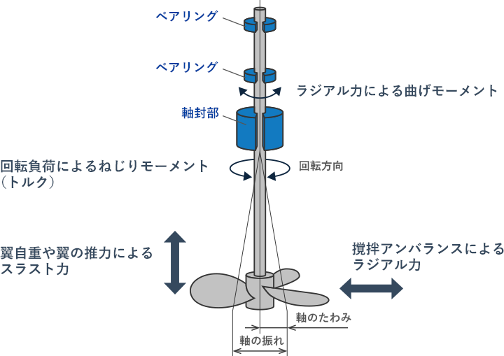
In general, an agitator is a rotating machine having a long agitator shaft supported at one side only (overhanging support condition).
So, it is required to provide stable mechanical strength enough for the operating condition.
On the mechanical design to decide the shaft diameter, all loading conditions acting the impeller and shaft should be taken into considerations, not only the torque to rotate the impeller, but also radial force due to unstable liquid flow in the tank, counter axial force due to impeller thrust force.
In addition, it's very important to avoid a risk of the resonance phenomenon, which will be induced in the condition that a natural frequency of the agitator shaft and the rotating speed of the agitator is close. Because the resonance phenomenon causes a dangerous condition with excessive vibration and may make a leaking from mechanical seals and critical damage to the shaft.
However, excessive large shaft diameter makes the agitator cost higher. So, Foot Bearing, which supports the bottom end of the shaft, can be provided to make the smaller shaft diameter.
In any way, the suitable design of the agitator shaft is important in the total viewpoint of the agitator design including the reliability and lifetime.
Loading condition to the agitator shaft
Mixing Tank
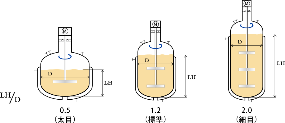
The shape of the mixing tank (sometimes, it is called as reactor, vessel, tank, autoclave…) is expressed in the ratio of LH (Liquid Height) / D (Tank Diameter). And it's said that the suitable figure will be LH/D=1.0 to 1.5.
In the case of a larger LH/D ratio, that means slender proportion, the uniformity in the tank tends to get worse for the mixing of middle-high viscosity range liquid. On the other hand, in the case of a smaller LH/D ratio, means fat proportion, the tank wall thickness needs to be thicker to withstand the retaining pressure.
So, for scale-up design, the tank shape needs to be investigated to make suitable conditions for all related factors like mixing, heat transfer, gas velocity, etc.
As for the tank bottom, it is common to apply 2:1 ellipsoidal head shape from the viewpoints not only the strength as a pressure retainer but to make a smooth mixing flow pattern that can avoid the stagnant region.
And, tank internal parts, such as coils, nozzles, baffles, etc they will be provided depends on the purpose. When installing such parts, it is required to make reliable mechanical strength without obstructing the mixing flow pattern.
Different shapes of tanks
-
Mixing Course
Beginner
course -
- Introduction Basic terms of mixing
- Course 1 Basics of basics: Three points to understand mixing
- Course 2 Examples of the purposes of mixing
- Course 3 Viscosity is the unit of stickiness
- Course 4 Consider a mixing vessel as a huge viscometer
- Course 5 Can you see the flow from power change? (Part 1)
- Course 6 Can you see the flow from power change? (Part 2)
- Course 7 Learn the essence of the mixing Reynolds number
- Course 8 Basics of basics of scaling up
- Course 9 Basics of scaling up
- Course 10 What is heat transfer performance in a mixing vessel?
- Course 11 What is film heat transfer coefficient , hi?
- Course 12 Mixing course review
-
Mixing Course
Practical
course -
- Introduction Mixing course SEASON II
- Course 1 Immediately determine the basic specifications of the mixing vessel using three pieces of information: operating liquid volume, viscosity and density.
- Course 2 Find a plan to improve the productivity of the mixing tank on the existing production line! (Part 1)