Practical course 3:Find a plan to improve the productivity of the mixing tank on the existing production line! (Part 2)
Course 3Find a plan to improve the productivity of the mixing tank on the existing production line! (Part 2)
In the previous part, we discussed simulations related to improving the productivity of mixing tanks, but analysis technology is merely a tool for problem-solving.
First of all, it is important to identify the true issues (problems to be solved) that are preventing the improvement of the operational rate of the production line. Once the problems are clear, we can use various tools to solve them.
In this second part, let’s discuss “What are the issues with equipment and operations that hinder stable operation?”
Drill sergeant's order: The cleaning time inside the mixing tank is too long! Productivity is low! Improve it!
In the previous part, one of the purposes of conducting simulations was mentioned as "reducing adhesions inside the tank". However, simulations cannot visually reproduce the adhesions situation.
First, it is necessary to obtain field feedback to understand why adhesions occur and connect this to the existing equipment and operational issues.
Without delay, the young engineer, Blendy, visited the customer's production plant to listen to the voices from the field.
Customer
Since there are a lot of adhesions, could you resolve the issue with a simulation at Sumitomo?
Blendy
What are the locations, amounts, and characteristics of the adhesions?
Hmm, my boss told me to cut the cleaning time in half, but we've actually outsourced it to a specialist company, so we don't have clear records on the adhesions situation. I'm just considering trying a simulation...
Despite acknowledging that adhesions are a major issue, it is often the case that only the cleaning contractor knows the most about the situation. Sigh, with this, we can't even begin to assume the mechanism of adhesions formation.
Alright, let's begin by walking you through the thought process of a manufacturing engineer as they narrow down the issues step by step.
Thought Process
1. Reconfirm the assumptions of the production process and equipment.
2. Understand the adhesions situation on the production site.
3. Identify the adhesion mechanism from the adhesion locations.
Step 1: Reconfirm the assumptions of the production process and equipment.
First, let's go back to basics and organize the assumptions of the subject under consideration.
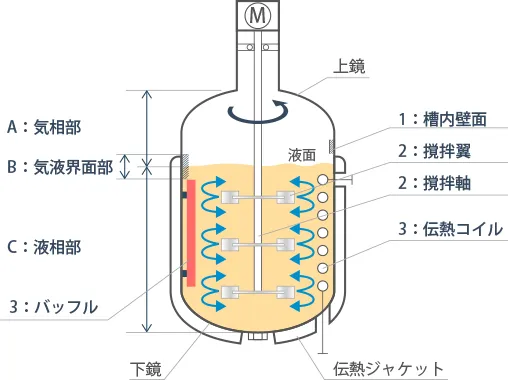
Figure 1 shows the structure of a typical mixing tank. If possible, it would be good to review the equipment drawings and confirm with your colleagues on-site.
The following seven items are important points that engineers should listen to in the field when trying to understand the image of adhesions
1) What is the operation method of the target mixing tank: batch or continuous?
2) What are the operating temperature, pressure, fluid viscosity, and density?
(Do they change during operation?)
3) Are there any operations involving powder addition, gas injection, or boiling state?
4) Is there a change in liquid level? (Is there data showing the relationship between operating time and liquid volume in the tank?)
5) Is there any adhesion to the rotating agitator shaft and blades?
6) Are there any internals (heat transfer coils or baffles), and what is their adhesion status?
7) Is the adhesion on the inner wall of the tank widespread or localized?
If localized, where exactly?
Figure 1. Structure of a Mixing Tank
Step 2: Understand the adhesions situation in the field.
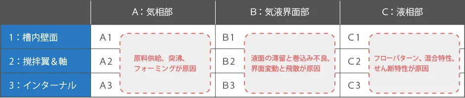
Table 1 shows the adhesion locations inside the tank with their major causes.
It is often said that "the truth is found on the ground," and experienced engineers can visualize the manufacturing process just by hearing about the adhesion situation inside the tank.
Every phenomenon in front of us is the result of a specific cause.
When discussing adhesion issues, it is often assumed that they occur in the liquid phase section (the area in contact with the process fluid) as shown in column C of the table. However, adhesion issues in columns A and B also frequently occur on site.
In any case, it is necessary to understand and classify the adhesion situation.
Table 1. Adhesion Locations and Main Causes
Step 3: Identify the adhesion mechanism from the adhesion locations.
With the conditions organized and on-site verification completed, let's introduce some of the thought processes engineers use to infer the causes.
A: In case of adhesion in the gas phase zone
In the gas phase section of the tank, there are fewer opportunities for contact with the process fluid. Therefore, the cause of adhesion is expected to be specific factors unique to the situation, such as operating methods, rather than the flow of the liquid.
Cause ① for A1
If adhesion is concentrated near the nozzles at the top head, it is caused by liquid drips from the fed material or powder scattering during raw material feed.
Countermeasure
Improve the raw material feed method or consider implementing a feed nozzle design, such as an insert pipe structure.
Cause ② for A1
If adhesion occurs over the entire surface of the top head, it is caused by bumping or splashing during boiling polymerization.
Countermeasure
Reevaluate the liquid level and boiling conditions (temperature and vacuum pressure) to prevent bumping.
Cause ③ for A1
If adhesion occurs around the entire circumference of the tank shell, it is caused by foaming during aeration or degassing.
Countermeasure
Review the gas velocity and consider using defoaming impellers or antifoaming agents.
Cause for A2 & A3
The cause is splashing liquid due to the agitator during changes in liquid level.
Countermeasure
Reevaluate the relationship between the liquid level and the position of the impeller and internals.
B: In case of adhesion in the Gas-Liquid interface section
Cause for B1
The cause is the stagnation of liquid free surfaces in high-concentration slurry or high-viscosity fluids.
Countermeasure
Increase the flow velocity at the tank wall surface by reconsidering the rotation speed.
Cause for B2
The cause of adhesion to the shaft is the poor circulation flow at the liquid surface, which cannot incorporate the fed raw powder materials into the liquid.
Countermeasure
Optimize the rotation speed and the distance from the liquid surface to the top of the impeller.
Cause for B3
The cause is the splashing of circulation flow at the internals.
Countermeasure
Optimize the rotation speed and the distance from the liquid surface to the top of the internal parts.
C: In case of adhesion in the Liquid phase zone
For parts that are constantly submerged in process fluids, the flow velocity and shear distribution of the overall circulation flow formed by the interaction between the impeller and internals often becomes an issue.
Generally, the idea tends to be, "Let's simulate it because adhesion can occur in the stagnant areas with slow flow velocity downstream of the baffle," but in reality, various adhesion problems arise depending on the manufacturing process.
For entire surface adhesion in fluid-contacting areas, there are equipment-based countermeasures such as polishing the wetted metal surfaces, applying fluoropolymer coatings or glass linings, and using anti-adhesion agents. Here, here we will introduce three cases of adhesion causes that are likely to be highly influenced by blending way.
In the case of 'liquid-liquid operations'③ Preventing adhesion is not simply a matter of vigorous mixing!
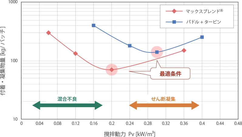
Generally, synthetic rubber and latex production lines (especially emulsion polymerization) are said to be in a daily battle against adhesion. Figure 2 shows the change in the amount of adhesion and agglomerates per batch when the rotation speed is varied using two types of impellers in an emulsion polymerization tank. Both impellers tend to show an optimal mixing condition range that is convex downward.
Figure 2. Relationship between Mixing Intensity and Amount of Adhesion/Agglomerates
The mechanism of aggregate formation in typical emulsion polymerization is as follows.
1. Low Mixing Power zone (left side of the figure): The mixing intensity is too weak, resulting in insufficient formation of overall circulation flow, which leads to the formation of stagnant areas and causes adhesion and aggregation.
2. High Mixing Power zone (right side of the figure): The mixing intensity is too strong, causing adhesion and aggregation due to shear aggregation in the high shear field near the impellers.
In this type of root cause analysis, evaluating the distribution of flow velocity and shear using the simulations introduced in the previous section can be an effective tool.
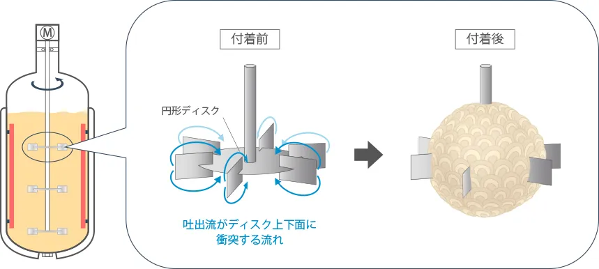
Figure 3 illustrates an instance of shear-induced agglomerates adhering to a disk turbine impeller during emulsion polymerization.
After several months of continuous operation, there were cases where the disk turbine impeller became covered in basketball-sized latex agglomerates. It is impressive how the agglomerate had grown close to the outer edge of the turbine blade.
Generally, adhesion is believed to be caused by poor mixing, leading to the assumption that increasing the impeller rotation speed and mixing more vigorously will solve the problem. However, it should be kept in mind that different mechanisms can cause adhesion and aggregation depending on the specific process.
Figure 3. Example of Shear Aggregation in Continuous Operation
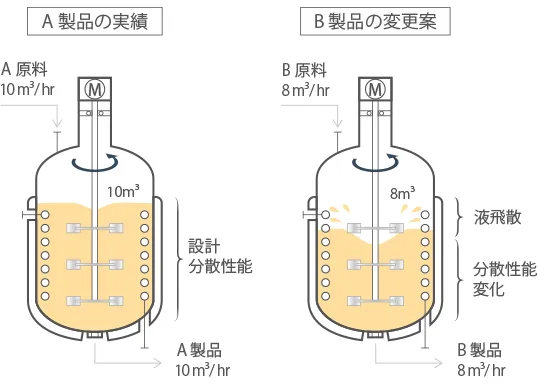
Example in "Solid-Liquid Operations": Easily changing the operating liquid level can increase adhesion?
This is an example that occurred at a chemical company.
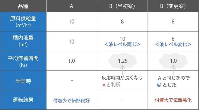
When switching the product being produced in the continuous operation process from Grade A to Grade B, it became necessary to reduce the production capacity by about 20%. To address this, if the raw material of feed rate for continuous operation was reduced and the holding liquid volume in the mixing tank remained the same as for Grade A, the reaction time (average residence time in the tank) for both grades would change, as shown in Table 2. Therefore, instructions were given to reduce the holding liquid volume by 20%, as shown in Figure 4, to maintain the same residence time during operation.
Figure 4. Relationship Between Impeller position and Liquid LevelTable 2. Comparison of Average Residence Time
However, once the actual operation of Grade B began, despite not changing other conditions such as the impeller rotation speed, the increase in adhesion inside the tank during operation led to a decrease in heat transfer performance, significantly shortening the possible continuous operation period. After various investigations, it was found that the flow pattern of the multi-stage paddle impeller had changed due to the lowered liquid level, worsening the suspension conditions inside the tank. This resulted in adhesion to the tank walls and coils, which led to a rapid fouling in heat transfer performance.
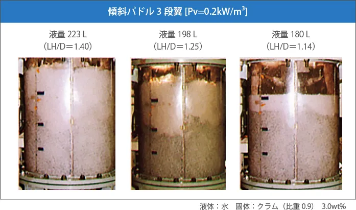
Photo 1 shows the suspension of floating clumps during changes in liquid level with a multi-stage paddle impeller. At the designed liquid level, sufficient suspension is achieved, but it is important to note that even slight changes in the liquid level can often lead to poor suspension.
Photo 1. Comparison of Suspension State During Liquid Level Change
Example in "Gas-Liquid Operation": When gas (bubbles) is mixed into the liquid, the discharge flow of the impeller is buffered, leading to poor mixing.
In a case where the productivity of a plant is determined by the ability to remove reaction heat (cooling performance) in the mixing tank, it is usually improved by increasing the heat transfer area of jackets and coils to enhance heat removal capacity.
However, when scaling up the tank while maintaining geometric similarity, it is theoretically impossible to keep the heat transfer area per unit liquid volume constant. This is because the liquid volume increases with the cube of the tank diameter ratio, whereas the heat transfer area only increases with the square of the tank diameter ratio. Therefore, in large mixing tanks, boiling reactions using reflux condensers may be employed to compensate for the insufficient heat removal with the latent heat of vaporization.
However, in a condition where many bubbles exist in the liquid, forming a gas-liquid two-phase flow, the bubbles cushion the discharge flow from the impellers. This can disrupt the originally stable circulating flow due to the bubbling effect
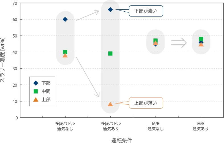
Figure 5 compares slurry suspension under boiling conditions simulated by aeration. It shows slurry concentration differences with and without aeration for multi-stage paddle Impeller(left) and MAXBLEND(right).
From this graph, we can see that even with the same mixing conditions, the slurry concentration varies significantly.
In large PVC suspension polymerization reactors over 50m3, it has been reported that increasing the reflux rate and operating in an excessively boiling condition can lead to poor product quality due to inadequate slurry suspension. Therefore, in mixing systems where it is difficult to form a stable vertical circulation flow in response to changes in the liquid level, such as with multi-stage paddle impellers, care must be taken not to use latent heat excessively.
Figure 5. Comparison of Dispersion Conditions with and without Aeration
In conclusion, we have discussed the potential causes (issues) related to adhesion.
Can you imagine what the mixing conditions inside the agitator tank at your plant are like?
Are you able to explain the adhesion mechanism to your supervisor?
Instead of worrying at your desk, it might be a good idea to go to the site, listen to the voices of the production team and cleaning contractors, and sort out the issues related to adhesion in your equipment while having lively discussions.
Over 20 years ago, someone from a chemical company said, "When I was a student, all I had to do was solve the problems given to me, but as an adult, I have to find and solve problems on my own." This statement struck me deeply.
In school exams, the skill required is to solve "given problems" in a short time, but in the real world, problems are not always presented with ready-made solutions.
In companies, the skill required is to identify "what the real problem is on-site," create specific tasks, and instruct subordinates on improvements. "Problems do not fall from the sky for corporate engineers."
Isn't it more exciting to solve problems you have discovered yourself than those given to you by others?