


Distillation & Liquid-Liquid Extractor Column-in-column
- HOME
- Products & Solutions
- Distillation & Liquid-Liquid Extractor
- Column-in-column
Energy-efficient & Low-carbon
Column-In-Column (CIC) represents an advanced, next-generation distillation column. Compared with conventional multi-column systems used in distillation units, CIC provides greater efficiency, which in turn reduces CO2 emissions.
- Lower CAPEX
- A conventional distillation unit consist of two or three columns to separate a three component process. But a CIC can be combined it into a single column.
- Few utility equipment & piping resulting in smaller foot print.
- Lower OPEX
Flow Image
CHECK POINT Combining multiple columns into a single column
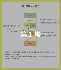
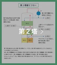
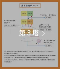
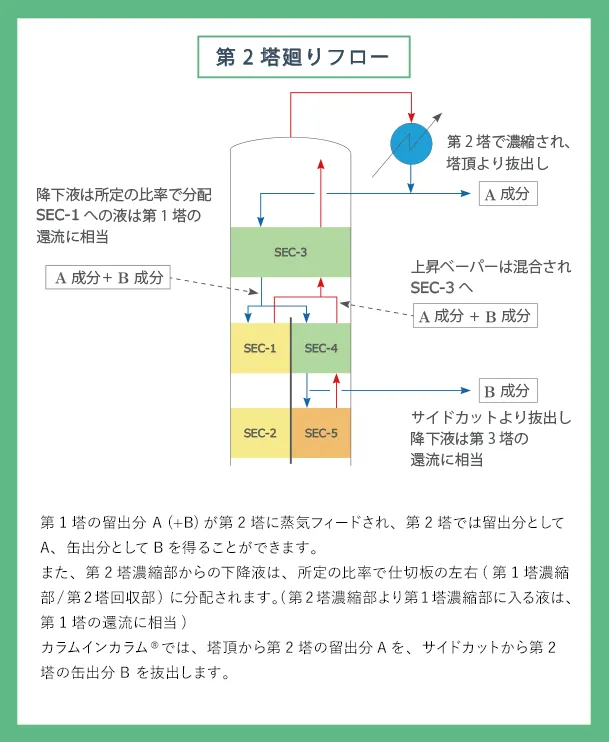
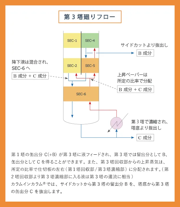
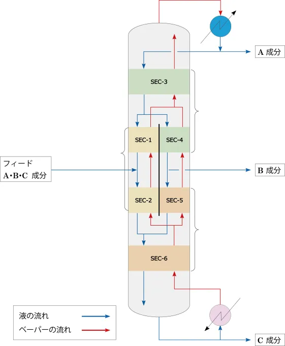
The defining characteristic of Column-In-Column is the vertical wall that divides the interior of the column into two distinct sections. As a result of this vertical wall, a single Column-In-Column can accommodate the functions of three columns.
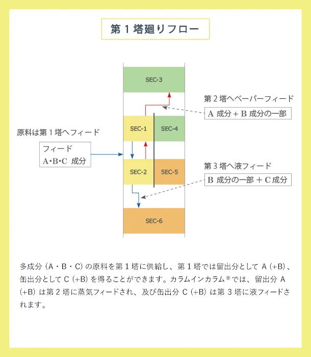
The figure on the right shows liquid and gas flow inside Column-In-Column.
The figure on the under shows liquid and gas flow inside Column-In-Column.
Click on each column to see the internal column flow mechanism.
This mechanism enables the separation of three-component system using a single Column-in-Column.


Principle and Effect of Energy Saving
A conventional distillation system with multiple components requires several columns for the separation of components, resulting in significant operational costs due to the high utility consumption of numerous reboilers and condensers in the system.
The fundamental concept of the Column-In-Column system is derived from the Petlyuk column model, which consists of a primary column and a pre-fractionator.
The assumptions are as follows;
- 1.
- The molar latent heat of vaporization of each component is equal.
- 2.
- The feed temperature is at its boiling point.
- 3.
- Only latent heat is taken into account, while sensible heat is neglected.

Subsequently, the condensers of Column 1 and Column 2 are consolidated, as are the reboilers of Column 1 and Column 3.
The resulting heat balance is as follows:
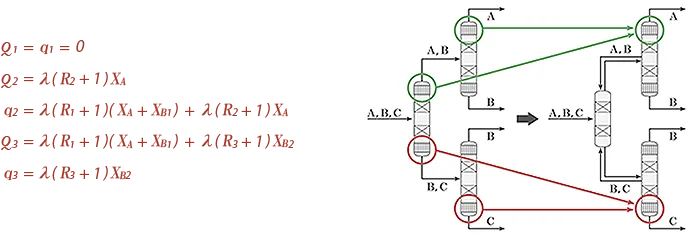
When the bottom product of Column 2 and the overhead product of Column 3 are both rich in component B, and Q2=q3 are balanced,
these two columns can be unified into a single column, and the resulting heat balance is as follows:

On comparing STEP 1 to STEP 3, it is evident that the heat duty of the reboilers and condensers in STEP 3 is reduced by λ(R2+1)XA compared to that of STEP 1.
For these reasons, the Column-In-Column design results in decreasing both utility usage and energy consumption.
References: Hajime Nishimura, et al. Journal of Chemical Engineering of Japan, 32, No.2. 134 (1968)
CHECK POINT Energy-Saving Effect
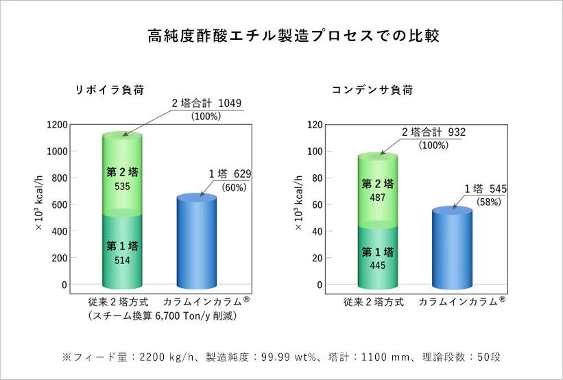
The chart compares heat duties of reboilers and condensers of conventional columns and the Column-In-Column system for high-purity ethyl acetate production process.
Column-In-Column can save energy by around 40%.
INFORMATION Related Information
-
 Plant Engineering
We propose our best performance with integration of our engineering solution and our core technologies, those are substantiated with our several decades career in the plant engineering fields.
-
 Technical Services
We support the study of distillation process and/or propose process improvement at the initial planning stage or basic design stage.
We can offer various services, such as process proposal with process simulator and pilot plant test with actual process liquid etc.


