


Distillation & Liquid-Liquid Extractor SFLOW series
Outstanding separation performance
over a wide range of operation.
By selecting and utilizing different types, makes it possible to cater to wide range of operations, ranging from minimum to high liquid volumes.
A prominent characteristic is that the equipment can be readily scaled up and can operate with minimal pressure drop.
SFLOW chatacteristics
SFLOW features a unique configuration and surface treatment that allows it to exhibit outstanding separation performance over wide range of liquid volumes operations, ranging from minimum to maximum.
SFLOW types are designated by a number that represents the specific surface area: 125, 250, 350, 500, or 750 (m2/m3), along with X (30°) or Y (45°), which denotes the angle of the packing corrugations in relation to the vertical.
By appropriately selecting and utilizing these different types, makes it possible to cover a wide range of operating conditions.
When substituting a current column packings to enhance throughput, SFLOW 250MX, 125MY, and 125MX types are recommended. Additionally, for increasing the number of theoretical stage with the same packing height, viable options available are 350MY and 500MY types.
The 250MY type is the most versitile and frequently utilized type.
CHECK POINT 01 Mechanical properties
SFLOW is categorized into two main types. The first type is produced from metal sheet, while the second type is composed of wire mesh.
Furthermore, the SFLOW lineup consists of a total of 11 types, which are defined by the specific surface area and the corrugation angle. The mechanical characteristics of each type are presented in Table 1.
| No | Type | Material | Specific Surface Area | Angle of Corrugated sheet | Thickness of Metal Sheet | Unit Weight | Height of One Element | NTSM (*) |
HETP (*) |
Pressure Drop per a Theoretical Stage (*) |
Maximum Hight of One Bed (*) |
Feature | Remarks | |
|---|---|---|---|---|---|---|---|---|---|---|---|---|---|---|
| m2/m3 | - | mm | kg/m3 | mm | 1/m | mm | kPa | mm | Capacity | Performance | ||||
| 1 | 125MX | Metal Sheet | 125 | 30° | 0.2 | 100 | 230 | 0.7 | 1500 | 0.45 | 12190 | High Capacity | Lower Theoritical stage | |
| 2 | 125MY | Metal Sheet | 125 | 45° | 0.2 | 200 | 215 | 1.0 | 1000 | 0.30 | 10105 | |||
| 3 | 210MX | Metal Sheet | 210 | 30° | 0.1 | 100 | 230 | 1.3 | 800 | 0.24 | 12190 | |||
| 4 | 210MY | Metal Sheet | 210 | 45° | 0.1 | 100 | 215 | 1.8 | 550 | 0.17 | 11180 | |||
| 5 | 250MX | Metal Sheet | 250 | 30° | 0.1 | 100 | 230 | 1.7 | 600 | 0.18 | 10120 | |||
| 6 | 250MY | Metal Sheet | 250 | 45° | 0.1 | 100 | 215 | 2.2 | 450 | 0.14 | 9030 | Standard Type | ||
| 7 | 350MY | Metal Sheet | 350 | 45° | 0.1 | 140 | 215 | 2.9 | 350 | 0.11 | 5590 | |||
| 8 | 500MY | Metal Sheet | 500 | 45° | 0.1 | 200 | 210 | 3.3 | 300 | 0.09 | 3570 | |||
| 9 | 750MY | Metal Sheet | 750 | 45° | 0.1 | 300 | 210 | 4.0 | 250 | 0.08 | 2100 | Higher Theoritical Stage | ||
| 10 | 500G | Gauze Type | 500 | 30° | - | 250 | 170 | 4.0 | 250 | 0.08 | 3570 | Ultra High Performance | especially under the high vacuum condition | |
| 11 | 700G | Gauze Type | 700 | 45° | - | 350 | 159 | 6.7 | 150 | 0.05 | 2067 | Low Capacity | Ultra High Performance | especially under the high vacuum condition |
(*) Data for Reference
Table 1. SFLOW packing properties
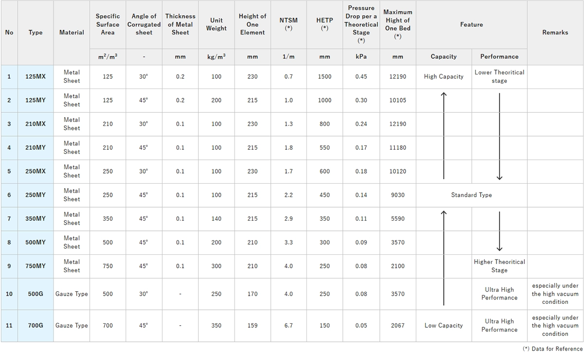
In Table 1, the initial three digits in the Type designation represents the surface area (m2) per 1m3 of filling volume. The letter M or G followed by number denotes the material of construction, where M indicates sheet metal (M for METAL) and G represents wire mesh (G for GAUZE). Subsequently, the letters X or Y indicate the angle of the corrugated sheet in relation to the vertical axis of the tower, with X corresponding to 30 degrees and Y to 45 degrees.
The column is filled by stacking packing material by one layer (one level) at a time, with the height of each layer, referred to as an element, differs based on the specific packing Type.
For instance, the "250MY" model features a surface area of 250m2 per 1m3 of filling capacity, is composed of sheet metal, has corrugated sheets positioned at a 45-degree angle, and each element has a height of approximately 215mm. Additionally, based on the packing installation method, each packing type can be categorized into an "Integrated Type" (monoblock type) that is directly installed into the column via the column body flange opening. Alternately, "Split Type" is carried into the column through a manhole and assembled within the column. It is important to note that "Split Type" are produced except 700G type.
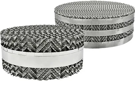
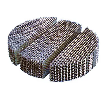
The metal sheet of M type features grooves on its surface along with holes positioned at appropriate intervals to facilitate effective gas-liquid interaction. The wire mesh is constructed by interweaving wires with a diameter of 0.2 mm or less through a specialized technique, which promotes more efficient gas-liquid contact compared to the sheet type. It also has a suitable holes arrangement, similar to that of the sheet type.
In both configurations, the material is ultimately processed and formed into a zigzag wave shape, and by adjusting the pitch of these folds, products with varying surface areas can be produced. The standard materials utilized are SUS304 or SUS316L. The typical appearance and shape of these types are illustrated in Figures 1 and 2.
CHECK POINT 02 Performance characteristics(NTSM and F-FACTOR)
It is evident that the key performance parameter of structured packing include HETP (Height Equivalent to a Theoretical Plate), which refers to the packing height necessary to achieve one theoretical plate, and (another parameter) is pressure drop per unit of packing height, ΔP/m. Among these two indicators, HETP is illustrated in Figures 3A and 3B.
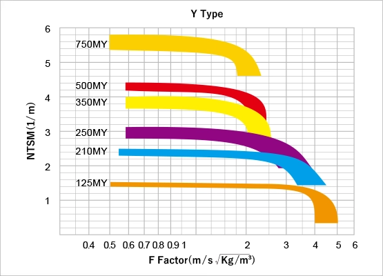
SFLOW MY-Type NTSM correlation diagram
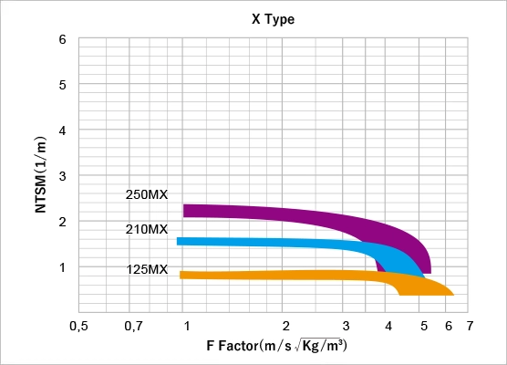
SFLOW MX-Type NTSM correlation diagram
Both Figures presents a comparison of the performance of each "sheet" type. Figure 3A shows performance of the Y type and Figure 3B shows performance of the X type. The horizontal axis of Figures 3A and 3B represents the gas velocity factor, referred to as "F-Factor", which is defined by the following formula.
F-FACTOR = UG*(ρG)0.5
UG: Superficial Gas Velocity(m/sec),
ρG: Gas Density(kg/m3)
The vertical axis denotes the reciprocal of HETP, which represents the number of theoretical stages per meter (NTSM), meaning the number of effective theoretical stages for each meter of packing height.
Figure 3A, illustrates that within a specific range of F-FACTOR, an increase in the specific surface area of the packing "type" corresponds to a higher NTSM value. This is to be expected, as a large specific surface area enhances efficient of gas-liquid interaction.
Conversely, there exists a threshold at which NTSM starts to decline, and as the specific surface area increases, the F-FACTOR at this threshold decreases. In simpler terms, if the approach to the flooding point remains unchanged, a larger specific surface area corresponds to a lower permissible gas velocity. Additionally, Figure 3B illustrates the relationship for the X-type with the same "sheet" configuration. In comparison to the Y-type, the X-type features a more steeper angle of the corrugated sheet in relation to the vertical axis of the column, facilitating liquid flow downwards; in other words, it possesses configuration that enhances gas passage, thereby allowing for a higher gas velocity. However, this results in a slight reduction in gas-liquid contact efficiency, leading to a lower NTSM value.
As previously stated, NTSM exhibits a correlation with F-FACTOR for every model, with each model having distinct design points.
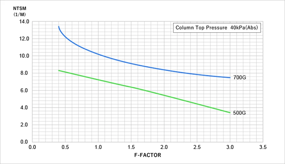
The performance characteristics of the G type (wire mesh type) are also shown in Figure 4. Figure 4 shows that the NTSM is higher and the type has better performance than the "sheet" type.
These correlations derived from actaul measurements conducted with standard test liquids such as ethylbenzene and chlorobenzene. Table 1 shows the standard design values for NTSM or HETP pertaining to general organic substances for each type.
CHECK POINT 03
Performance characteristics
(pressure drop and flooding gas velocity)
The flooding point is defined as the moment when the gas velocity increses and the NTSM approaches to zero, while the gas velocity corresponding to a pressure drop of 1 kPa per meter of packing height is referred to as the flooding gas velocity.
The threshold at which the NTSM starts to decrease is desingated as the upper limit of the design gas velocity, which is defined as the point where the pressure drop per meter reaches 0.3 kPa. Typically, the actual maximum design gas velocity includes an additional margin of error, ranging from 0.8 to 0.9 of the permissible upper limit. In this scenario, the design point approaches the flooding point by 40 to 60%. Figure 5 shows the pressure drop ΔP/m per meter of packing height for each type category.
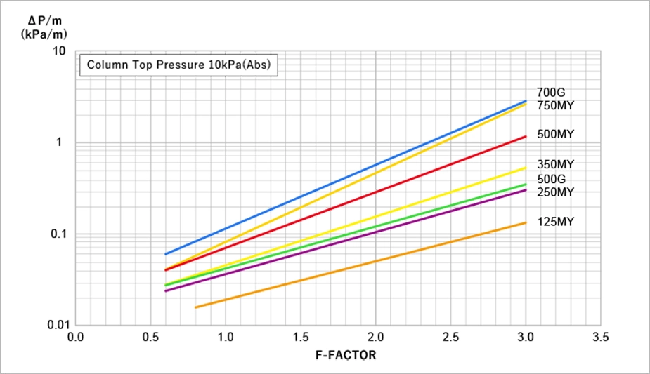
For a same gas velocity (F-FACTOR), an increase in specific surface area results in a higher ΔP/m, while the F-FACTOR corresponding to the upper design limit of ΔP/m = 0.3 kPa decreases as the specific surface area increses.
CHECK POINT 04 Performance characteristics (liquid hold-up)
The liquid Hold-Up ratio within the packed bed (the ratio of the retained liquid volume to the total packing volume) increases as the liquid load becomes higher. This relationship is illustrated in Figure 6.
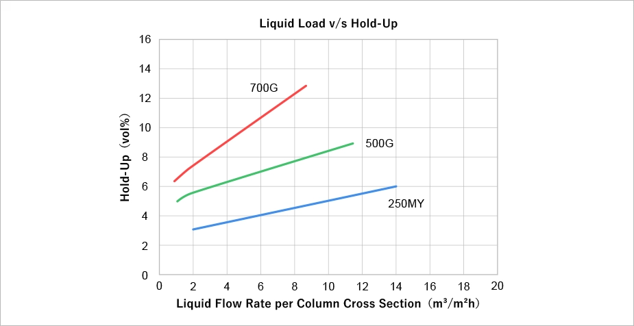
The dynamic holdup rate shown in Figure 6, is dynamic holdup rate, while the static holdup rate is negligible to be ignored. The wire mesh design facilitates greater liquid retention compared to the sheet type, thereby enhancing gas-liquid contact efficiency, albeit leading to a higher holdup rate. Furthermore, the holdup rate remains significantly lower than that of trays, approximately 30% to 50% of the tray holdup rate.
INFORMATION Related Information
-
 Plant Engineering
We propose our best performance with integration of our engineering solution and our core technologies, those are substantiated with our several decades career in the plant engineering fields.
-
 Technical Services
We support the study of distillation process and/or propose process improvement at the initial planning stage or basic design stage.
We can offer various services, such as process proposal with process simulator and pilot plant test with actual process liquid etc.


